DIY Whole-Home Energy Monitor with ESP32 and CT Clamps: Build Guide
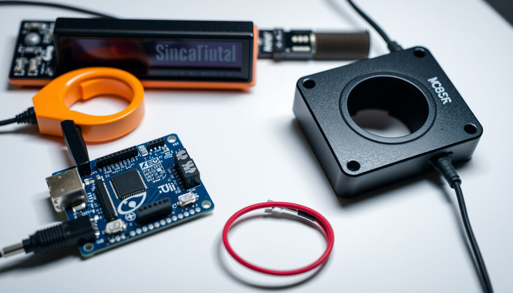
A whole-home energy monitor that keeps every reading on your own hardware is a compelling self-hosting project: CT clamps sense each circuit’s current, an ADS1115 digitizes the signal, an ESP32 runs ESPHome, and Home Assistant logs the result. This guide is assembled from official documentation, vendor datasheets, and community build reports — we did not build this unit ourselves. Read the safety section before anything else.
What this build does (and doesn’t)
This build routes current through non-invasive CT clamps into an ADS1115 ADC and an ESP32 running ESPHome, which reports per-circuit current to Home Assistant, as documented in the ESPHome CT Clamp sensor docs; because there is no voltage reference, power is estimated at an assumed nominal voltage, and reactive, DC power, and direction are not measured.
The signal chain is: SCT-013 voltage-output clamp (0–1 V) → ADS1115 16-bit ADC over I²C → ESP32 → ESPHome → Home Assistant. What you get is local, cloud-free, per-circuit current data. What you do not get is metered-reality accuracy: with no voltage reference, wattage is derived by multiplying measured current by an assumed nominal mains voltage, so it is an estimate. The dardhal field report is explicit that this approach does not measure reactive or DC power and does not indicate direction (import versus export).
Safety first: this involves mains work
Mains safety governs this build: CT clamps are non-invasive and encircle one conductor only (live or neutral, never both) without cutting the wire, and because panel work is mains work, the breaker must be switched off and verified dead before any access, with a licensed electrician hired if unsure. The one-conductor placement rule and the “qualified people only” warning come from the sources; the breaker and electrician advice is this guide’s own safety guidance.
⚠️ MAINS SAFETY — READ BEFORE STARTING
- CT clamps are non-invasive: open the clamp and place it around ONE conductor only — live OR neutral, never both — and never cut the wire.
- Any work at a consumer unit (panel) is mains work: switch the breaker off, verify the circuit is dead, and hire a licensed electrician if you are unsure.
- Never bridge conductors. Never connect the ESP32 or ADS1115 to mains voltage. The electronics see only the low-voltage CT output.
- Per the ESPHome ADS1115 docs, the AIN pins must never exceed VDD + 0.3 V — that is ≤ 3.6 V on a 3.3 V supply.
The field report’s author issues the same warning to readers: do not attempt this if you are not familiar, comfortable, or qualified to work with AC voltage. The source material establishes no safety-standard numbers, so none are cited here.
How CT current sensing works
Current sensing relies on a current transformer: the OpenEnergyMonitor CT sensor primer explains how a CT induces a proportional secondary current, and the YHDC SCT-013 datasheet (MakerHero copy) distinguishes voltage-output models (0–1 V, built-in sampling resistor) from the current-output SCT-013-000 (0–50 mA), which needs an external burden resistor and bias circuit and is excluded here.
In short, the clamp’s ferrite core senses the magnetic field around a conductor and produces a small output. Voltage-output SCT-013 models deliver 0–1 V with a built-in sampling resistor and are the only type this build uses. The sources do not establish whether that AC output needs a DC bias before the ADC, so check it against the ESPHome docs and your own wiring before powering up. The current-output SCT-013-000 requires an external burden resistor and bias circuit, so it is not suitable for a plain ESP32 ADC build. Useful datasheet physical facts: a 13 mm × 13 mm opening, 1 m leads with a 3.5 mm three-core plug (a 2.5 mm audio-plug variant is listed as optional), a −25 °C to +70 °C operating range, and a 180° switching angle.
Parts you need
The bill of materials is deliberately generic: a 38-pin ESP32 dev board, an ADS1115 four-channel 16-bit ADC breakout, one voltage-output SCT-013 clamp per circuit, shielded 3.5 mm jack harnesses, a USB power supply, and Home Assistant with the ESPHome integration; the SCT-013 datasheet’s model list supplies the sizing rule below.
| Component | Specification |
|---|---|
| ESP32 dev board | Generic 38-pin dev board (exact part numbers are unverified in the sources) |
| ADC breakout | ADS1115, 4-channel, 16-bit |
| CT clamps | SCT-013 voltage-output 0–1 V models only, one per circuit, sized per the rule below |
| Leads | 1 m leads with 3.5 mm three-core plug (shielded wire or matching harness) |
| Power | USB power supply for the ESP32 |
| Software | Home Assistant with the ESPHome integration |
Model-selection rule (from the datasheet’s model list): expected branch current must sit in the 10–120% linear band, where the datasheet specifies ±3% non-linearity. A 20 A branch therefore suits a 20 A or 30 A clamp. Voltage-output models only: SCT-013-005, -010, -015, -020, -025, -030, -050, -060, and -000V (0–100 A, 0–1 V). Never the current-output SCT-013-000.
Wiring: CT clamps to ADS1115 to ESP32
Signal and ground from each clamp’s 3.5 mm plug land on an ADS1115 input (A0 through A3) and GND, the ADS1115 runs from the ESP32’s 3.3 V rail, SDA and SCL connect to the board’s I2C pins (confirm against your pinout — unverified here), and ADDR ties to GND for the 0x48 default address.
| Connection | From | To |
|---|---|---|
| CT plug signal wire | 3.5 mm jack (verify assignments with a multimeter continuity check first — it is a three-core plug) | ADS1115 A0, A1, A2, or A3 (one clamp per channel) |
| CT plug common | 3.5 mm jack | ADS1115 GND |
| VDD | ESP32 3V3 | ADS1115 VDD |
| GND | ESP32 GND | ADS1115 GND |
| SDA / SCL | ESP32 I²C pins — confirm against your board’s pinout; specific GPIOs are unverified in the sources | ADS1115 SDA / SCL |
| ADDR | GND → address 0x48 (default); VCC → 0x49 for a second hub (SDA → 0x4a, SCL → 0x4B per the ADS1115 docs) | ADS1115 ADDR pin |
Do the continuity check before powering anything, keep every AIN pin at or below VDD + 0.3 V (≤ 3.6 V on a 3.3 V supply), and remember the clamp itself never touches the electronics — only its low-voltage output leads do.
The ESPHome configuration
The ESPHome configuration combines an i2c bus, an ads1115 hub at address 0x48 with continuous_mode enabled per the official docs, an ads1115 source sensor on multiplexer A0_GND with gain 6.144, and a ct_clamp sensor reading it with the 200 ms default sample_duration, 60 s default update_interval, and a calibrate_linear filter.
i2c:
  sda: GPIO21   # common ESP32 default, not confirmed in the sources — check your board's pinout
  scl: GPIO22   # common ESP32 default, not confirmed in the sources — check your board's pinout

ads1115:
  - address: 0x48            # ADDR pin to GND; ADDR to VCC = 0x49 for a second hub
    continuous_mode: true    # ESPHome docs: "Please enable this for the Ct Clamp component"
    # See the conflict note below before relying on this on your hardware.

sensor:
  - platform: ads1115
    multiplexer: 'A0_GND'    # CT plug signal; A1_GND / A2_GND / A3_GND for the other clamps
    gain: 6.144              # options: 6.144 / 4.096 / 2.048 / 1.024 / 0.512 / 0.256 (V full-scale)
    name: "Raw CT Voltage"
    id: ct_adc

  - platform: ct_clamp
    sensor: ct_adc           # required: id of the source sensor
    name: "Circuit 1 Current"
    sample_duration: 200ms   # default; 10 whole cycles on a 50 Hz system
    update_interval: 60s     # default; must be greater than sample_duration
    filters:
      - calibrate_linear:
          - 0 -> 0
          - 0.1333 -> 4.0    # EXAMPLE values from the ESPHome docs — replace with your own pair
Notes: multiplexer options include A0_GND through A3_GND plus paired inputs such as A0_A1; the ADS1115 sample rate defaults to 860 SPS; and update_interval must exceed sample_duration.
The continuous_mode conflict: docs vs field report
The ESPHome ADS1115 docs say to enable continuous_mode for the ct_clamp component. The dardhal field report — an eight-circuit ESP32 + ADS1115 + SCT-013 build — states the opposite: with continuous_mode plus ct_clamp, updates were “very slow updating and unreliable (mostly wrong).” The author’s working approach was to disable continuous_mode, compute RMS voltage with an ESPHome filter, and map RMS volts to current with a scale factor (for a 20 A / 1 V clamp, 100 mV = 2 A). This is a genuine conflict, not settled fact. Suggested path: start with the documented configuration (continuous_mode: true) because it is the official guidance; if updates are slow or readings look wrong on your hardware, reproduce the field report’s alternative and verify the results yourself against a known load.
Home Assistant integration steps
Integration is a five-step flow: add the ESPHome node through the ESPHome integration, accept the auto-discovered sensors, derive power at an assumed nominal voltage (explicitly labeled an estimate), optionally add a utility meter for long-term statistics, and optionally pipe data into InfluxDB and Grafana as the field report describes.
- In Home Assistant, open the ESPHome integration and add the new node (it should also auto-discover after first connect).
- Accept the auto-discovered sensors — the raw ADS1115 voltage and the calibrated ct_clamp current entities.
- Derive power by multiplying current by your assumed nominal mains voltage, and label the resulting entity as an estimate in your UI.
- Optionally add a utility meter or long-term statistics sensor for daily/monthly tracking.
- Optionally replicate the field report’s pipeline: Home Assistant → InfluxDB → Grafana for graphing.
Calibration with a known load
Calibration uses a known load: divide the load’s nameplate watts by the nominal mains voltage to get expected amps (an estimate), read the raw logged value from ESPHome, then build calibrate_linear from the mandatory 0 -> 0 pair plus your measured-to-known pair — the docs’ example is 0.1333 -> 4.0 — recompile, upload, and recheck.
- Power a known resistive load (for example, a heater or lamp bank) on the monitored circuit.
- Compute expected current: nameplate watts ÷ nominal mains voltage = expected amps. Treat this as an estimate, since actual mains voltage varies.
- Read the raw logged current value in ESPHome logs or Home Assistant for that clamp.
- Build the
calibrate_linearfilter from0 -> 0plus your measured→known pair. The docs’ worked example: a known 4.0 A load logged as 0.1333 A, giving- 0 -> 0and- 0.1333 -> 4.0. - Recompile, upload to the ESP32, and recheck the reading against the same known load. Repeat if the error is still unacceptable.
What this DIY build does and does not do
Scope is limited to the DIY path. No prebuilt monitor is benchmarked here, and no head-to-head measurements exist in the sources used.
| Capability | This build | Limit |
|---|---|---|
| Sensing | Non-invasive current via SCT-013 clamps | Current only, no voltage reference |
| Power | Estimated from current × assumed nominal voltage | Not a metered-reality reading |
| Data path | Local ESPHome → Home Assistant | No cloud dependency in this design |
| Calibration | User calibration with calibrate_linear and a known load | Needs a known load and repeat checks |
| Not measured | — | Reactive power, DC power, import/export direction |
For a prebuilt option, see our home energy monitoring setup guide; this page does not repeat it.
FAQ
Four questions recur in community builds: whether the ESP32’s own ADC can replace the ADS1115 (the field report says no, citing low-voltage non-linearity), which SCT-013 model to buy, why low loads read wrong or near zero, and whether the system measures real power or solar export direction (it does not).
Can I skip the ADS1115 and use the ESP32’s ADC? The field report states the ESP32’s internal ADC is non-linear and unreliable below roughly 100–150 mV, making the bottom ~10% of a 1 V CT output unusable — on a 5 A clamp that means no readings below about 0.75 A (≈170 W). The report therefore recommends the ADS1115; verify on your own hardware.
Which SCT-013 should I buy? Choose a voltage-output 0–1 V model (suffixes -005 through -060, plus -000V for 0–100 A) sized so expected branch current stays in the 10–120% linear band, where the datasheet specifies ±3% non-linearity — a 20 A branch suits a 20 A or 30 A clamp. Never use the current-output SCT-013-000, which needs an external burden resistor and bias circuit.
Why do low loads read wrong or near zero? Two known sources of error are the ADC and the continuous_mode setting. This build uses an ADS1115, not the ESP32’s own ADC, so the field report’s low-end ADC problem does not apply directly. The ESPHome docs recommend enabling ADS1115 continuous_mode for ct_clamp, while that same report found the combination “very slow updating and unreliable (mostly wrong)”; disabling it and computing RMS via a filter worked for the author. Verify on your hardware.
Does this measure real power or solar export direction? No. Without a voltage reference, the build measures current only; power is derived by multiplying current by an assumed nominal mains voltage, so it is an estimate. The field report explicitly notes the approach does not measure reactive or DC power and does not indicate direction, so it cannot confirm solar export flow on its own.
The Bottom Line
The bottom line is that this architecture offers maximum local control and flexibility for competent DIYers, at the cost of comfort with mains-adjacent work and responsibility for user calibration; the sources are explicit that it is not a metered-reality instrument, since power is estimated from current alone at an assumed nominal voltage.
For a self-hoster who wants per-circuit visibility inside Home Assistant with no cloud dependency, this gives fully local control with user calibration — but it demands honest calibration against known loads, tolerance for the continuous_mode conflict, and respect for the mains-safety rules above. If any of that is uncomfortable, a commercial monitor is the appropriate tool.
How This Guide Was Built
This guide is assembled from official documentation, vendor datasheets, and community build reports — we did not build this unit ourselves.
Primary sources: the ESPHome ct_clamp docs, the ESPHome ADS1115 docs, and the YHDC SCT-013 datasheet. Community source: the dardhal ESP32-ADS1115 field report, an eight-circuit build. Items the sources do not establish (prices, part numbers, GPIO assignments, version numbers) are left out or marked as yours to confirm.
📖 Related Reads
- CodeIntel Log — code quality, debugging, and software engineering benchmarks
Cross-links automatically generated from SmartHome Field Guide.
← Back to guides